7 Experiment: Attitude Using a 6/9 axis IMU#
This section explores examples similar to section 5 but using real data. Initially using a gyroscope and an accelerometer, a 6 axis IMU, and later using a magnetometer as well, a 9 axis IMU. The 6 axis example uses the MPU6050 with an arduino controller and the 9 axis example used the mobile phone sensors with the sensor logger app.
Implementation#
The code for this section can be found here. The main file is Analysis.py which contains AnalyseMPU class which is the parent class for AnalysePhone and AnalyseTest, these read data from the MPU6050, sensor logger and test data (from section 5) respectively.
Raw Data from MPU6050#
Each file with measurements came with its own calibration file, which was used to determine the offset in each direction. Different tests were performed with the MPU6050, the data for these are contained in the folders:
YawPitchRoll: Involves fast oscillations in the yaw direction followed by a short break, then oscillations in the roll direction followed by a short break, then oscillations in the pitch direction.FullYaw: Contains data where the MPU6050 was rotated in a full circle in the yaw direction and then rotated back in the opposite direction.FullPitch: Contains data where the MPU6050 was rotated in a full circle in the pitch direction and then rotated back in the opposite direction.
Warning
Currently the Kalman filter will only correctly fit YawPitchRoll data. When the sensor was rotated beyond \(180^o\) in the yaw and roll directions or beyond \(90^o\) in the pitch direction the Kalman filter will need to re-normalize the attitude, which made it difficult to fit the Kalman filter. This wasn’t a problem with YawPitchRoll data as no full rotations were performed.
Raw Data From Sensor Logger#
The data collected can be found here. Each folder contains a different test and contains the following files:
In all cases time was measured in seconds.
Gravity.csv: Contains the acceleration readings without the acceleration due to gravity removed. The x, y and z components are measured in ms\(^{-2}\).Magnetometer.csv: Contains the magnetometer readings in the phone’s frame of reference. The x, y and z components are measured in \(\mu\)T.Gyroscope.csv: Contains the gyroscope readings in the phone’s frame of reference. x, y and z are measured in radians rads\(^{-1}\)Orientation.csv: Contains the orientation of the phone in yaw-pitch-roll measured in radians. We will refer to this as the true orientation as its the orientation calculated by the phone. All other files are not used in this analysis.
Tests were performed and stored in the folders:
PitchRollCalibration: Fast movement in the pitch direction followed by a short break, then motion in a combination of the pitch and roll directions followed by a short break, then motion in just the roll direction, this was the same test as in section 5.YawRollPitchCalibration: Contains data for a calibration test where the phone was moved in each direction alone followed by a short pause.FullYaw: Contains data where the phone was rotated in a full circle in the yaw direction and then rotated back in the opposite direction.FullPitch: Contains data where the phone was rotated in a full circle in the pitch direction and then rotated back in the opposite direction.
Programme structure#
The programme is structured with three files:
AdvKalman.py: Contains the Kalman filter implementation and handles the conversion between quaternions and Euler angles.OrientationKalman.py: Contains therunfunction which runs the Kalman filter on the data and returns the filtered signal, Euler angles from the accelerometer and gyroscope, and the magnetometer readings. It acts as an interface between Analysis.py and AdvKalman.py.Analysis.py: Contains theAnalysePhoneclass which is used to read in the data, run the Kalman filter and plot the results.
Theory, 9 axis#
In section 5 gyroscope data and accelerometer data were fused to determine the attitude of the phone. However the accelerometer on its own was unable to measure the yaw direction. When phone is lying flat in the xy plane \(z^\psi\), can be determined easily:
Where \(m_x\) and \(m_y\) are the x and y components of the magnetometer reading. The magnetometer reading is in the phone’s frame of reference this is normally not the xy plane so the accelerometer data to is required to write the corrected magnetometer readings \(m_x'\) and \(m_y'\).
Where \(z^\phi\) and \(z^\theta\) are the roll and pitch angles calculated using the accelerometer.
Then as before \(z^\psi\) and \(z^\phi\) were calculated using the accelerometer and were used to correct \(z^\psi\) when the magnetometer isn’t lying flat in the xy plane. To summarize the update measurement will be formed from the accelerometer, for pitch and roll and the magnetometer for yaw. The prediction step will use measurements from the gyroscope in the same way as section 5.
Results#
Fast Yaw Pitch Roll#
These examples involved fast oscillations in the yaw directions followed by a short break, then oscillations in the roll direction followed by a short break, then oscillations in the pitch direction.
Note
Here yaw-pitch-roll is normalized as follows: yaw is in the range \([-\pi, \pi]\), pitch is in the range \([-\pi/2, \pi/2]\) and roll is in the range \([-\pi, \pi]\).
MPU6050 6-axis IMU#
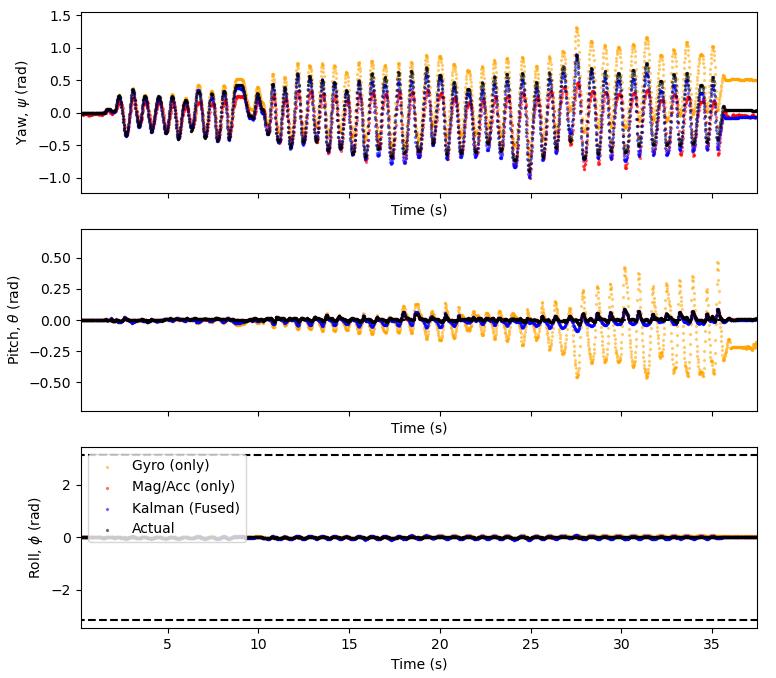
So that the correction was normalized the correction in the yaw direction was set to always be zero, the pitch and roll directions came from accelerometer measurements. The prediction came from gyroscope measurements.
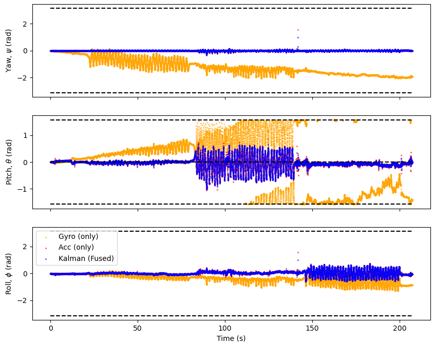
Fig. 28 Fast oscillations in the yaw, roll and pitch directions. The orange line is the measurements from integrating the angular velocities from the gyro and red line is the measurements from the accelerometer. The blue line is the Kalman filtered attitude which fuses data from the gyroscope and accelerometer/magnetometer.#
The drift is clearly visible from the gyro. But the accelerometer measurements seem to be much more accurate. However it is unclear if Kalman filter improves on the accelerometer measurements with the current \(Q\) and \(R\).
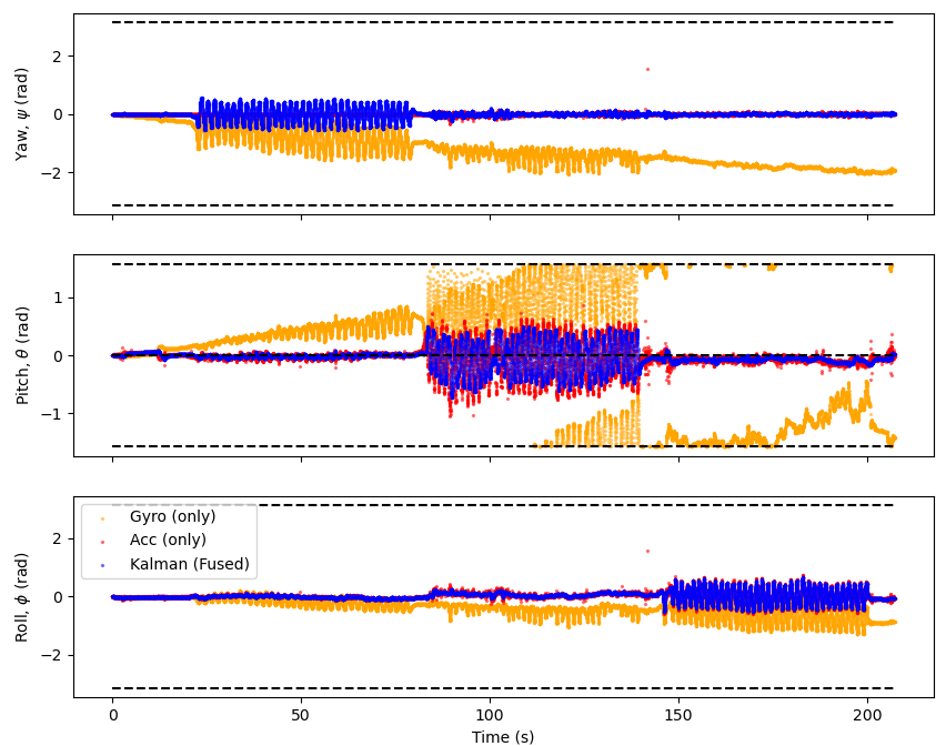
Fig. 29 The same data as Fig. 28 but with the Kalman filter tuned, with larger \(R\) and smaller \(Q\), increasing the weighting on the prediction, the gyro data.#
Here the Kalman filter has a much better shape for the yaw direction since there is a greater weighting on the prediction meaning oscillations from the gyro are much more pronounced in the Kalman filter. The Kalman filter also still filters out the drift from the gyro data making it a very accurate fit.
There is a problem in the oscillations in all directions are now delayed as the gyroscope is slower to to changes than the accelerometer, hence by putting more faith in the prediction although the fit more accurately resembles the shape of the true data it is slightly delayed.
The Kalman filter is able to filter out some of the noise from the accelerometer data. The accelerometer data is typically noisier than the gyroscope data, so putting more emphasis on the gyroscope will help to filter out noise.
Phone, 9-axis IMU#
Introducing magnetometer measurements means there is 2 measurements for each axis, reducing the total drift.
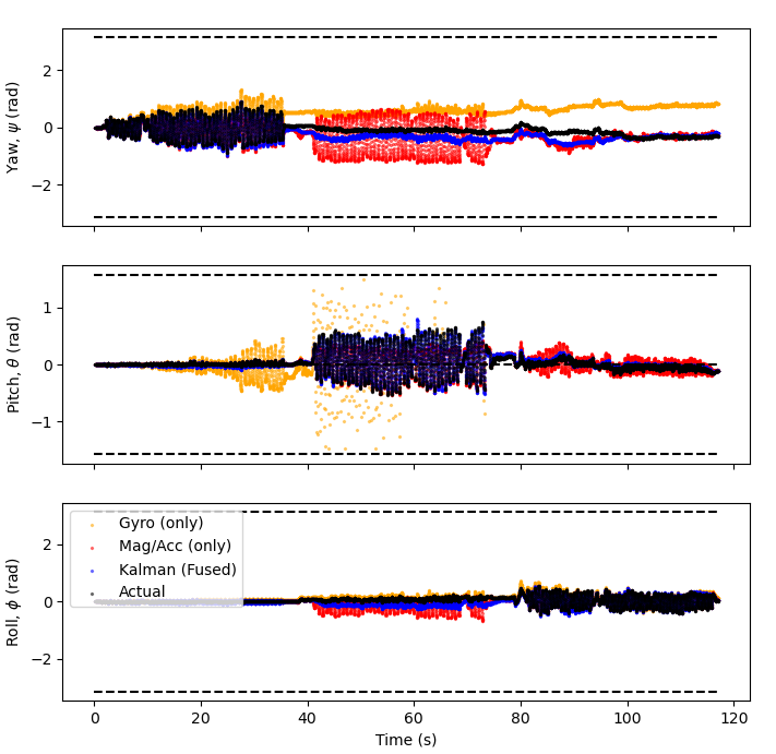
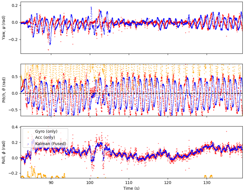
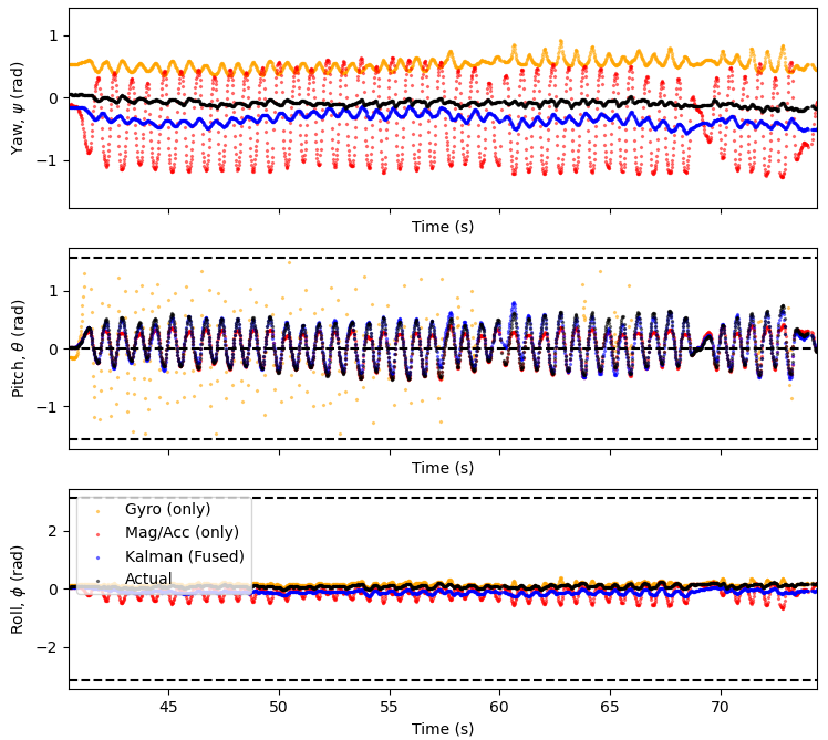
Fig. 31 Fast oscillations in the yaw, roll and pitch directions. The orange line is the measurements from integrating the angular velocities from the gyro and red line is the measurements from the magnetometer and accelerometer. The blue line is the Kalman filtered attitude which fuses data from the gyroscope and accelerometer/magnetometer. The black line is the phones own attitude measurements.#
There is significant drift in the measurements from the gyro alone the end measurements from the gyro alone has drifted by approximately \(60^o\) from the true value where as the Kalman filter and the magnetometer/accelerometer data are much better fits. Also the amplitude of the measurements oscillations in the roll direction is much smaller than the yaw and pitch directions. This was because its because of the way the phone had to be held.
Here the Kalman filter is able to correct for both the drift from the gyro and noise from the magnetometer making it a very good fit for yaw. The is interference with the gyroscope in the pitch direction but the Kalman filter successfully filters this out.
There is interference in the magnetometer/gyroscope measurements but the Kalman filter filters this out successfully but this does cause drift in the Kalman filter measurements. The gyroscope measurements for Pitch are incredibly noisy possibly due to oversensitivity of the gyroscope in the phone, but the Kalman filter remains a good fit. The Roll direction remains fairly stable.
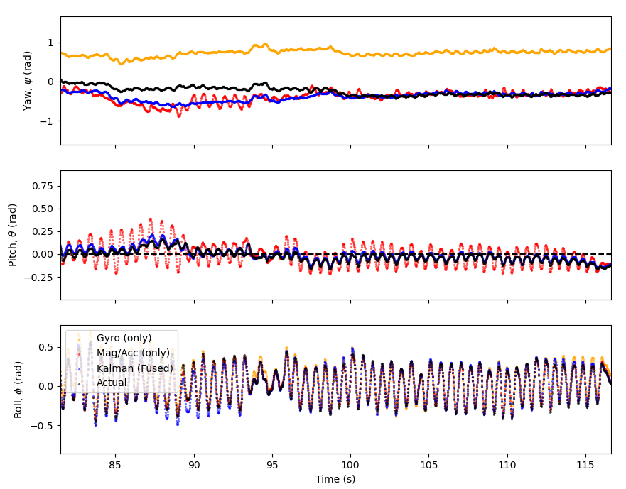
For the yaw direction both sets of instruments are indicating the correct shape but there is drift especially in the gyro. There is interference in the pitch direction, again the Kalman filter does a good job of filtering this out.
Full Rotation, Yaw#
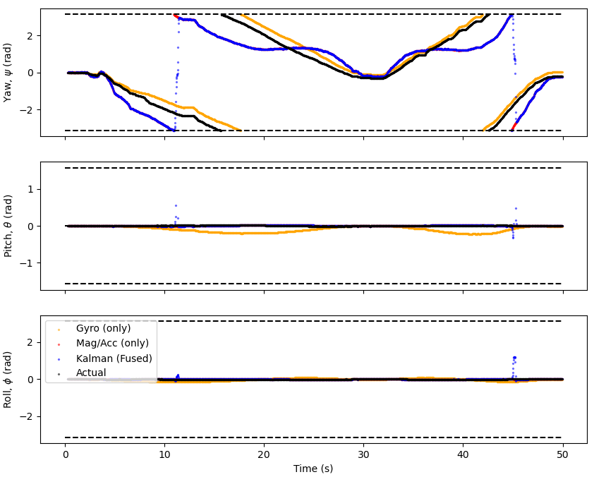
Fig. 35 The phone was rotated in a full circle in the yaw direction and then rotated back in the opposite direction. The orange line is the measurements from integrating the angular velocities from the gyro and red line is the measurements from the magnetometer and accelerometer. The blue line is the Kalman filtered attitude which fuses data from the gyroscope and accelerometer/magnetometer. The black line is the phones own attitude measurements.#
The Kalman filter is able to reduce noise in the magnetometer measurements but the gyroscope seems to provide the best fit here. This could be because the magnetometer is overly sensitive. However it’s plausible that the phone reliable more on its gyroscope for measurements of orientation since magnetometer data isn’t as reliable due to additional magnetic fields meaning it can be poorly calibrated. Whereas a gyroscope with a small amount of drift will always work.
Note
I didn’t have enough time during the placement to test the Kalman filter for full rotations.